
Suspension problems often develop gradually and go unnoticed until they affect handling, tire wear, or vehicle stability. This step-by-step guide walks through the full diagnostic process using manual tools and your own AutoSolo gauge, no expensive alignment rack required.
Tools You Will Need
Required Tools
- AutoSolo Camber & Caster Gauge (ASCGAL, ASDCG203, or ASCCKG)
- Floor jack
- Jack stands (2 or 4)
- Tape measure
- Pry bar
- Tire pressure gauge
- Level surface: garage floor, concrete driveway, or workshop floor
Optional but Helpful
- Turn plates, recommended for caster measurement in Step 7
- AutoSolo Ramp Levels, an at-home alternative to alignment shop turn plates
- AutoSolo ASSTL1 Steering Wheel Level
- AutoSolo ASSWH1 Steering Wheel Holder
- Flashlight
- Notepad or phone to record measurements
Step 1: Park on a Level Surface and Prepare Vehicle
Good suspension diagnosis starts with establishing a stable and neutral baseline. Taking the time to properly prepare the vehicle prevents false conclusions and gives you readings you can trust.
Inspect Wheels and Tires
Before any measurements, inspect all four wheels and tires:
- Inspect rims for bends or cracks
- Check tires for bulges, excessive wear, or uneven wear patterns
- Confirm all four tires are the same size and in similar condition
Important: These issues must be resolved before checking alignment. A bent wheel will produce false camber readings.
Choose a Properly Level Surface
Avoid sloped driveways, uneven asphalt, gravel, or inclined parking areas. Even small surface angles can shift vehicle weight distribution and produce misleading ride height and camber readings. If necessary, use a digital level on the floor to confirm it is level.
Tip: If you have turn plates, park the front wheels over them now. They will be needed for caster measurement in Step 7.
Perform a Quick Bounce Test (Pre-Check)
Push down firmly on the fender above each wheel and release. The vehicle should rise smoothly, settle back to its resting position within one bounce, and stop. If any corner continues bouncing or oscillating, the shock absorber on that corner is likely worn. Note this for further evaluation in Step 9.
Check and Equalize Tire Pressure
Use a tire pressure gauge to check all four tires and adjust to manufacturer specifications, typically 32 to 36 PSI for most passenger vehicles. The exact specification is on the driver door jamb sticker or in the owner's manual. A tire underinflated by 10 PSI can lower that corner of the vehicle enough to falsely indicate a suspension issue.
Simulate Typical Weight Distribution
Vehicle weight distribution affects suspension geometry. Simulate typical occupant loads, keep typical cargo in the vehicle, and ensure the fuel tank is approximately half full. This ensures measurements reflect the vehicle's actual operating condition rather than an unloaded baseline.
Center the Steering Wheel
The steering wheel must be fully centered before taking any suspension measurements. Even a small steering angle changes camber and caster readings and can produce false diagnostic results.
- Sit in the driver's seat.
- Attach the AutoSolo ASSTL1 Steering Wheel Level to the steering wheel.
- Rotate the steering wheel slowly until the level reads centered.
- Confirm the front wheels are pointing straight ahead visually.
Tip, Electric Power Steering: Some vehicles with electric power steering require the engine to be running to move the steering wheel. Some EPS systems may also shift the wheel slightly when the engine is turned off. If your vehicle has electric steering, center the wheel with the engine running, then roll the vehicle forward or backward approximately one foot after shutting off the engine to unload the steering and suspension.

Lock the Steering Wheel in Place
Once centered, install the AutoSolo ASSWH1 Steering Wheel Holder between the steering wheel and the driver seat. Adjust until it applies firm pressure. Even small steering movement can change camber readings by several tenths of a degree, enough to misdiagnose suspension damage.
Allow the Suspension to Fully Settle
Once the vehicle is parked, centered, and secured, wait approximately 1-2 minutes for internal suspension components, bushings, and springs to relax into their true static position. For the most consistent readings, gently roll the vehicle forward and backward 1-2 feet, then resecure and allow it to settle again.
Step 2: Measure Ride Height at All Four Corners
Ride height measurement is one of the most important early indicators of suspension health. Springs support the vehicle's weight, and suspension components maintain its position. When springs weaken, components bend, or bushings wear, the vehicle will no longer sit evenly.
Why Ride Height Matters
Ride height affects the entire suspension geometry. When ride height changes, it alters camber angle, caster angle, toe angle, and suspension travel range, making this a critical first diagnostic step before measuring camber and caster.
How to Measure Ride Height
Using a tape measure, measure from the ground vertically to the highest point of the wheel arch (fender) directly above the wheel center.
- Position yourself directly next to the wheel.
- Place the end of the tape measure flat on the ground beside the tire.
- Extend the tape vertically upward.
- Measure to the highest point of the wheel arch directly above the wheel center.
- Record the measurement.
Repeat for all four wheels: Front Left, Front Right, Rear Left, Rear Right. Measure as vertically as possible. Do not measure at an angle.
Tighter Readings: If tires differ in size or wear, measure from the center of the wheel hub to the top of the fender arch instead. This eliminates tire diameter as a variable and gives you a more consistent read on true suspension position.

Record and Compare Measurements
Always compare side-to-side (left vs. right). Front-to-back differences are normal by design and do not indicate a problem.
Example Readings. Front Left: 27.5 in. Front Right: 27.4 in. Rear Left: 28.0 in. Rear Right: 26.9 in. Rear side-to-side difference: 1.1 inches. This strongly indicates a suspension issue affecting the rear right corner.
How to Interpret Ride Height Differences
| Side-to-Side Difference | Assessment |
|---|---|
| 0.0 to 0.3 inches | Excellent, suspension likely healthy |
| 0.3 to 0.5 inches | Acceptable |
| Greater than 0.5 inches | Possible suspension issue, investigate further |
Step 3: Perform Initial Camber Measurement
This is the first measurement step. Camber is the angle at which the wheel tilts inward or outward relative to vertical when viewed from the front of the vehicle. Measuring camber immediately establishes a baseline and reveals suspension asymmetry that may not be visible during visual inspection.
Why Camber Measurement Is Critical
The suspension is designed to maintain consistent camber angles on both sides of the vehicle. When components bend, wear, or shift, camber changes as a direct result. Camber imbalance can indicate:
- Bent control arms
- Bent struts
- Worn or collapsed bushings
- Bent steering knuckle
- Subframe shift
- Structural damage from potholes, curbs, or collisions
- Camber adjustment out of specification (on vehicles with adjustable camber)
How to Measure Camber Using the AutoSolo Gauge
AutoSolo offers multiple Camber and Caster Gauge models. The core principle is the same: the gauge must be securely mounted to a true vertical reference surface on the wheel assembly, typically using the AutoSolo Wheel Clamp Adapter or by mounting directly to the brake rotor or hub face.
- Refer to your specific AutoSolo Camber & Caster Gauge model's instruction manual. Ensure it is properly zeroed and configured.
- Attach the gauge to the wheel assembly using the AutoSolo Wheel Clamp Adapter, brake rotor/hub face, or model-specific mounting hardware.
- Ensure the gauge is firmly secured and sitting flush against a clean, flat mounting surface free of debris, rust, or obstructions.
- Confirm the gauge is positioned vertically and fully stabilized. Do not hold the gauge by hand unless instructed by your model's manual.
- Allow the reading to stabilize.
- Record the camber measurement for the front left wheel.
- Repeat for the front right wheel.

Example Readings. Front Left Camber: -0.8°. Front Right Camber: -2.1°. Difference: 1.3°. The difference is significant and indicates a suspension issue affecting the right side.
How to Interpret Camber Differences
| Side-to-Side Difference | Assessment |
|---|---|
| 0.0° to 0.3° | Excellent, suspension likely healthy |
| 0.3° to 0.5° | Acceptable, minor variation |
| 0.5° to 1.0° | Possible suspension wear or minor damage |
| Greater than 1.0° | Strong indication of suspension damage |
Common causes: bent control arm, bent strut, worn bushings, bent knuckle, shifted subframe, camber adjustment out of specification, and accident or impact damage.
Why Measure Before Lifting the Vehicle
Measuring camber while the vehicle is resting under its full weight reveals the true operating geometry. If measured with the vehicle lifted, the suspension would hang freely, eliminating load and masking alignment problems. These baseline measurements will later confirm whether visible component wear corresponds with alignment abnormalities.
Step 4: Lift the Front of the Vehicle and Inspect Suspension Components
Once camber measurement has established whether a geometry imbalance exists, the next step is to inspect suspension components directly to identify the physical cause.
Safely Lift and Secure the Vehicle
- Position a floor jack under the manufacturer-recommended front lifting point on one side of the front.
- Slowly lift that side until the wheel is off the ground.
- Place a jack stand securely under the proper support point on that side.
- Lower the jack until the vehicle rests securely on the jack stand.
- Repeat for the opposite front side.
Safety: Never rely solely on the floor jack to support the vehicle. Ensure the vehicle is stable on both jack stands before proceeding.
Remove the Front Wheels (Recommended)
Removing the wheels provides better access and visibility to suspension components, allowing for a more thorough inspection of critical load-bearing parts.
Inspect Control Arm Bushings
Control arm bushings allow suspension movement while maintaining proper geometry. Worn bushings allow excessive movement, which changes camber and caster angles. Look for: cracked rubber, torn or separated rubber, dry rot, and excessive looseness. Healthy bushings should appear intact and firmly bonded.

Inspect Ball Joints
Ball joints allow the suspension to pivot while supporting vehicle weight. Ball joint wear directly affects camber and steering stability. Look for: torn dust boots, grease leakage, rust contamination, and excessive looseness.
Inspect Tie Rod Ends
Tie rods connect the steering rack to the wheels and maintain steering alignment. Worn tie rods allow wheel movement independent of steering input. Look for: torn boots, grease leakage, loose joints, and physical damage.
Inspect Struts and Shock Absorbers
Struts and shocks control suspension movement and maintain wheel contact with the road. Look for: oil leakage along the shaft, bent strut housing, physical damage, and loose mounting points. Oil leakage indicates internal seal failure. Bent struts directly affect camber angle.
Step 5: Check for Mechanical Play in the Suspension
After establishing baseline camber measurements and visually inspecting suspension components, check for mechanical play, unwanted movement between suspension and steering components that should remain tight. Any looseness allows the wheel to shift position under load, directly affecting camber, caster, and toe angles.
Test for Vertical Play: The 12 and 6 O'Clock Test
This test primarily checks the condition of ball joints and wheel bearings.
- Stand facing the wheel.
- Place one hand at the top of the tire (12 o'clock position).
- Place your other hand at the bottom of the tire (6 o'clock position).
- Firmly push inward with one hand while pulling outward with the other.
- Alternate pushing and pulling to feel for movement.
Normal: Wheel feels tight and solid with no noticeable movement or clicking.
Abnormal: Any noticeable movement or clicking may indicate worn ball joints, worn wheel bearings, or loose suspension mounting points.

How Vertical Play Relates to Camber
If you observed camber imbalance in Step 3 and vertical play is present during the 12 and 6 o'clock test, you have likely identified the root cause. Ball joint wear is one of the most common causes of camber instability because ball joints directly locate the wheel vertically and laterally. Loose ball joints or wheel bearings allow the wheel to move out of its intended alignment position under load.
Test for Horizontal Play: The 3 and 9 O'Clock Test
This test primarily checks the condition of tie rods and steering components.
- Place one hand at the left side of the tire (9 o'clock position).
- Place your other hand at the right side of the tire (3 o'clock position).
- Push inward with one hand while pulling outward with the other.
- Alternate pressure while observing movement.
Normal: Wheel feels firm and stable with no free movement.
Abnormal: Movement may indicate worn inner or outer tie rods, or steering rack looseness. Tie rods primarily affect toe, not camber.
Step 6: Perform Bushing Load Test Using Pry Bar
Bushings often fail internally without obvious visual signs. Even if they appear intact externally, the internal rubber may have softened, cracked, or separated. This allows excessive movement under load and directly affects camber and caster stability. The pry bar load test simulates real-world forces applied to suspension components while driving.
How to Perform the Bushing Load Test
With the vehicle safely supported on jack stands:
- Locate the control arm bushings where the control arm connects to the vehicle frame.
- Insert a pry bar between the control arm and the frame or mounting point.
- Apply moderate, steady pressure to load the bushing.
- Observe how much the control arm moves relative to the frame.

Note: Do not use excessive force. Moderate pressure is sufficient to reveal worn bushings.
Normal: Very minimal movement, firm resistance, smooth controlled motion.
Worn or Failed Bushing: Excessive movement, sudden shifting, clunking sound, or loose uncontrolled movement. The control arm should not move freely.
If Step 3 revealed camber imbalance and this test reveals worn bushings, you have confirmed the mechanical cause. Replacing worn bushings restores proper suspension geometry and alignment stability.
Step 7: Measure Caster Using the AutoSolo Camber and Caster Gauge
After confirming camber readings and inspecting for mechanical looseness, reinstall the wheels and lower the vehicle onto turn plates. Re-center the steering and allow the suspension to settle before measuring caster.
Caster is the forward or rearward tilt of the steering axis when viewed from the side of the vehicle. It plays a critical role in steering stability, straight-line tracking, and steering wheel return-to-center.
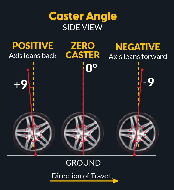
Why Caster Measurement Is Critical
Caster is one of the most revealing measurements for diagnosing bent suspension components or structural damage, because caster is not easily altered by adjustment on many vehicles. If caster differs significantly between sides, it almost always indicates bent or shifted components, not normal wear.
Caster imbalance can cause:
- Vehicle pulling to one side
- Steering instability and vague feel
- Poor steering wheel return-to-center after turning
- Uneven steering effort between left and right turns
Common causes: bent control arm, bent strut, bent steering knuckle, shifted subframe, and structural damage from impact or collision.
Special Equipment Required
Caster measurement requires the wheels to turn smoothly left and right while the suspension remains fully loaded. This requires turn plates or equivalent low-friction turning surfaces:
- Alignment shop turn plates (preferred)
- AutoSolo Ramp Levels (recommended alternative when working on the ground)
- Alignment rack turn plates (if using a shop rack)
Caster Measurement Process
Follow the instructions provided with your specific AutoSolo Camber & Caster Gauge model. The general workflow:
- Ensure the vehicle is positioned on turn plates.
- Confirm the steering wheel is centered and secured with the ASSWH1 Holder.
- Attach the AutoSolo Camber & Caster Gauge to the wheel per your model's instructions.
- Turn the steering wheel to the specified angle as instructed by your gauge model.
- Zero the gauge.
- Turn the steering wheel to the opposite specified angle.
- Record the reading.
Repeat for both front wheels. Always refer to your model's instruction manual for proper mounting method, steering angle requirements, measurement sequence, and reading interpretation.

Example Readings. Left Caster: 6.5°. Right Caster: 4.2°. Difference: 2.3°. This is a significant difference and strongly indicates suspension or structural damage affecting the right side.
How to Interpret Caster Differences
Caster does not need to be identical side-to-side. Many alignment specifications intentionally allow a small caster split to compensate for road crown: roads are slightly higher in the center to allow water drainage. A small amount of additional positive caster on the right side (in countries that drive on the right) helps counteract the vehicle's tendency to drift toward the road edge.
| Side-to-Side Difference | Assessment |
|---|---|
| 0.0° to 0.5° | Normal, within typical tolerances |
| 0.5° to 1.0° | Common OEM specification range, generally acceptable |
| Greater than 1.0° | Excessive, likely indicates suspension damage, can cause pull or return-to-center issues |
Caster imbalance greater than 1.0° almost always indicates a bent or shifted component rather than normal wear.
Step 8: Roll the Vehicle and Repeat Camber Measurement to Verify Suspension Stability
Once you have measured camber and inspected suspension components, verify whether the suspension maintains consistent geometry under normal movement. Some suspension problems only appear when the suspension is loaded, unloaded, or allowed to settle naturally.
Even if initial camber readings appear acceptable, worn bushings, loose joints, or bent components may allow the geometry to shift when the vehicle moves.
Procedure
- Roll the vehicle forward 1 to 2 feet, then allow it to settle for 1 to 2 minutes.
- Reattach the AutoSolo Camber & Caster Gauge following the same procedure used in Step 3.
- Measure camber again on both front wheels.
- Record and compare to your original measurements from Step 3.
How to Interpret the Results
Consistent (within 0.2° to 0.3°): Suspension is stable. Components are holding alignment properly.
Changing (greater than 0.5°): Indicates worn control arm bushings, loose ball joints, loose mounting points, bent suspension components, or structural instability. Repairs are necessary before alignment.
If camber readings change after rolling, it confirms that suspension components are allowing unwanted movement and repairs are necessary.
Step 9: Perform Bounce Test to Evaluate Shock Absorber and Damper Condition
Shock absorbers and struts control suspension movement and stabilize the vehicle after bumps, turns, and braking. While shocks do not directly set camber or caster angles, they play a critical role in maintaining consistent tire contact and stabilizing suspension geometry. Worn shocks allow excessive suspension movement, leading to unstable handling and inconsistent alignment behavior.
Procedure
- Stand at the front corner of the vehicle.
- Place both hands firmly on the fender, hood edge, or front corner above the wheel. Alternatively, place a knee on one corner of the bumper for leverage.
- Push downward firmly to compress the suspension.
- Release quickly and observe how the vehicle responds.
Repeat for both front corners, then the rear corners as well.

How the Vehicle Should Respond
Normal: Suspension rises up very slightly above its normal resting position once, returns to normal position, and does not oscillate.
Worn Shock Absorbers: Vehicle continues bouncing up and down with multiple oscillations before settling, or shows slow, uncontrolled recovery.
While worn shocks do not directly cause camber imbalance, they allow excessive suspension movement that leads to inconsistent alignment behavior while driving, reduced stability, uneven tire wear, and poor handling.
Complete Workflow Summary
By following this complete step-by-step process, you can diagnose suspension problems yourself using manual tools, no expensive computerized alignment equipment required.
| Step | Action |
|---|---|
| 1 | Prepare the vehicle. Inspect wheels and tires, park on a level surface over turn plates if available, perform quick bounce pre-check, equalize tire pressure, simulate typical weight loads, center steering using AutoSolo ASSTL1 and secure with ASSWH1. |
| 2 | Measure ride height at all four corners to identify spring or structural imbalance (compare side-to-side only). |
| 3 | Measure camber using the AutoSolo Camber & Caster Gauge to detect suspension asymmetry with the vehicle at full weight. |
| 4 | Lift and visually inspect suspension components for wear or damage, one corner at a time. |
| 5 | Check for mechanical play in ball joints (12/6 o'clock test), tie rods (3/9 o'clock test), and wheel bearings. |
| 6 | Perform pry bar load test to identify worn control arm bushings that pass visual inspection but fail under load. |
| 7 | Reinstall wheels, lower onto turn plates, and measure caster using the AutoSolo Camber & Caster Gauge. |
| 8 | Roll the vehicle and repeat camber measurement to confirm suspension stability under movement. |
| 9 | Perform bounce test to evaluate shock absorber and damper condition at all four corners. |
Why This Process Works
Many suspension problems cannot be identified through visual inspection alone. The combination of measurement and hands-on testing gives you the most complete diagnostic picture.
- Camber Measurement. Detects suspension asymmetry even when no visible damage exists. It is the first measurable sign of most suspension problems.
- Caster Measurement. Reveals structural asymmetry. Unlike camber, caster imbalance almost always indicates a bent or shifted component, not normal wear.
- Mechanical Play Testing. Confirms whether ball joints, tie rods, and wheel bearings are allowing unwanted wheel movement that changes alignment under load.
- Bushing Load Testing. Reveals internal bushing failure that is invisible to visual inspection but directly affects alignment stability while driving.
- Repeat Camber After Rolling. The definitive test for component stability. Confirms whether suspension holds alignment or shifts under real-world movement.
How to Tell the Difference
When camber or caster readings differ significantly between the left and right sides, the cause can be either an alignment condition or a mechanical suspension problem. Understanding the distinction is critical. You cannot align a vehicle with a broken suspension.
Alignment adjustments primarily affect toe, which is controlled by adjusting the tie rods. On vehicles with built-in adjustment points (cam bolts, eccentric bolts, or adjustable arms), camber may also be correctable through alignment. However, many vehicles do not have factory camber or caster adjustment.
Suspension problems primarily involve worn, loose, or bent components that cannot be corrected through alignment alone. Significant camber or caster differences on a vehicle without adjustment points usually indicate component damage.
How to Confirm the Difference. Perform a camber measurement, roll the vehicle forward to settle the suspension, then measure again with the AutoSolo Camber & Caster Gauge. If readings remain consistent, the suspension is stable and alignment adjustments may resolve the issue. If readings change after rolling, a mechanical problem must be repaired before alignment.
Quick Reference: What to Check When Angles Are Off
If Camber Is Off
- Check ride height first
- Inspect springs for sag
- Look for worn control arm bushings
- Check for bent struts or knuckles
- Verify subframe alignment
- Check camber adjustment if equipped
If Caster Is Off
- Look for worn control arm bushings
- Check for accident damage
- Inspect strut mounts
- Verify subframe position
- Check for aftermarket parts that shift geometry